30 amp manual transfer switch
Understanding 30 Amp Manual Transfer Switches
30 amp manual transfer switches offer a safe way to connect a generator to a home’s electrical system during outages.
These switches allow selective powering of essential circuits, avoiding backfeeding into the utility grid, and ensuring electrical safety.
They are a crucial component for backup power solutions, providing peace of mind during emergencies.
What is a Manual Transfer Switch?
A manual transfer switch is a vital electrical device designed to safely connect a portable generator to a home’s wiring system during a power outage. Unlike automatic transfer switches, it requires manual operation – you physically switch the power source from the utility grid to the generator.
Specifically, a 30-amp manual transfer switch is rated to handle a maximum load of 30 amps at 240 volts. This means it can support a selection of essential circuits, like those powering refrigerators, lights, and heating systems. It prevents dangerous backfeeding – electricity flowing back into the power grid – which could harm utility workers and damage equipment.
These switches feature a transfer mechanism that isolates the home from the grid while the generator is running, ensuring a secure and controlled power supply. They are a cost-effective solution for backup power, offering a reliable alternative to whole-house generators.
Why Choose a 30 Amp Transfer Switch?
A 30 amp transfer switch strikes a balance between cost-effectiveness and functionality, making it a popular choice for many homeowners. It’s ideal for powering essential circuits during outages, without the expense of a whole-house generator system. While supporting 240v circuits, individual breakers are limited to 20 amps.
This amperage rating is sufficient for running critical appliances, ensuring comfort and safety. Choosing a manual switch offers control – you decide when to switch power sources. It’s also a simpler installation compared to automatic systems, potentially reducing labor costs.
Furthermore, a 30-amp switch is compatible with a wide range of portable generators, both gas and battery-powered, offering flexibility in your backup power setup. It’s a practical solution for reliable, selective power restoration.

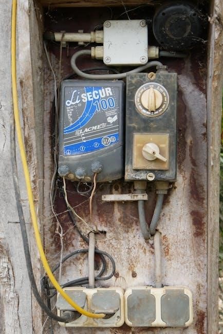
Key Components of a 30 Amp Transfer Switch
Key components include the transfer mechanism, circuit breakers with amperage ratings, a neutral busbar, and grounding terminals, ensuring safe and efficient power transfer.
The Transfer Mechanism
The transfer mechanism is the heart of the switch, physically disconnecting the home from the utility grid and connecting it to the generator’s power. This is achieved through a robust switching system, typically a lever or rotary dial, that directs power flow.
It ensures only one power source is connected at a time, preventing dangerous backfeeding. The mechanism isolates the generator from the grid, safeguarding utility workers and neighbors. Proper functioning of this component is vital for safe operation.
The switch’s design allows for a clear visual indication of which source—utility or generator—is currently powering the selected circuits, enhancing user awareness and control.
Circuit Breakers & Amperage Rating
Circuit breakers within the transfer switch protect connected circuits from overloads, just like those in your main electrical panel. A 30 amp transfer switch supports circuits with a maximum breaker rating of 20 amps each, even though the switch itself is rated for 30 amps.
This limitation ensures the total load doesn’t exceed the switch’s capacity. The amperage rating is crucial for matching the switch to your generator’s output. Selecting appropriately sized breakers prevents damage and ensures safe operation.
Understanding these ratings is essential for proper circuit allocation and avoiding potential electrical hazards during generator use.
Neutral Busbar and Grounding
A neutral busbar is a vital component within a 30 amp transfer switch, providing a common connection point for the neutral wires of circuits being transferred. Proper grounding is absolutely critical for safety, preventing electrical shock and ensuring the system functions correctly.
The transfer switch should include a ground box terminal for secure grounding. This connection safeguards against faults and ensures that any stray current is safely directed to the earth.
Always verify a solid ground connection during installation and regularly inspect it for corrosion or looseness. A properly grounded system is paramount for safe and reliable operation.
Installation Considerations
Installing a 30 amp transfer switch requires careful planning, including location selection, proper wiring, and adherence to electrical codes for safety.
Choosing the Right Location
Selecting the ideal location for your 30 amp manual transfer switch is paramount for a safe and efficient installation. Proximity to your existing electrical panel is crucial, minimizing the length of wiring runs and simplifying the connection process.
The location should be easily accessible for operation and future maintenance, but also protected from the elements and unauthorized access. Consider a dry, indoor space, avoiding areas prone to moisture or extreme temperatures.
Ensure sufficient space around the switch for comfortable and safe working conditions during installation and any potential troubleshooting. A well-ventilated area is also recommended to prevent overheating. Prioritize a location that complies with local electrical codes and allows for a secure mounting to a wall or suitable structure.
Wiring Requirements: L1, L2, R1, R2 Lines
Understanding the L1, L2, R1, and R2 lines is fundamental to correctly wiring a 30 amp transfer switch. These designations represent the hot legs of your electrical service – two for the main utility feed (L1, L2) and two for the generator feed (R1, R2).
The transfer switch isolates these circuits, allowing you to switch between utility and generator power. It’s vital to connect L1 to R1 and L2 to R2, ensuring a proper transfer.
Breaker amperage is limited to 20 amps even though the lines support 30 amps; Incorrect wiring can lead to dangerous situations, so meticulous attention to detail and adherence to wiring diagrams are essential. Always consult a qualified electrician if you are unsure about any aspect of the wiring process.
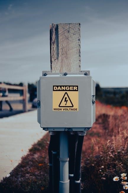
Outdoor Power Inlet Box Installation
Installing an outdoor power inlet box is a critical step in connecting your generator to the transfer switch. This box serves as the secure connection point for the generator’s power cord, protecting the connection from the elements.
The transfer switch installation kit typically includes this box, designed for connection to a pre-wired conduit leading indoors. Ensure the box is mounted securely and weatherproofed to prevent moisture intrusion.
Proper grounding of the inlet box is paramount for safety. This provides a path for fault currents, minimizing the risk of electrical shock. Always follow local electrical codes and manufacturer’s instructions during installation.
Dedicated 50 Amp Breaker & NEMA SS2-50P Outlet
A dedicated 50-amp breaker is essential for safely powering the transfer switch and, subsequently, the generator-supplied circuits. This breaker must be installed next to your main utility breaker within the electrical panel.
Correspondingly, a NEMA SS2-50P outlet needs to be installed adjacent to the panel. This heavy-duty outlet is specifically designed to handle the power input from a generator.
Wiring this outlet directly to the dedicated 50-amp breaker ensures a robust and safe connection. This setup prevents overloading the electrical system and protects against potential hazards during generator operation.

Connecting Your Generator
Generators, whether gas or battery-powered, can be used with this transfer switch, offering versatile backup power options for your home’s essential needs.
Ensure proper connection to the transfer switch for safe and efficient operation.
Generator Compatibility (Gas or Battery)
This 30 amp transfer switch demonstrates excellent compatibility with a wide range of generators, encompassing both traditional gas-powered models and increasingly popular battery-powered options. The versatility allows homeowners to select the generator that best suits their needs and preferences, considering factors like fuel availability, noise levels, and environmental impact.
Regardless of the generator type, it’s crucial to verify its wattage output aligns with the circuits connected through the transfer switch. The L1, L2, R1, and R2 lines support 30 amp breakers, but individual circuit breakers should not exceed 20 amps. This ensures safe and efficient power distribution during an outage, preventing overloads and potential damage to appliances or the electrical system.
Natures Generator support confirms compatibility and offers assistance via (800) 975-7909 or support@naturesgenerator.com.
Connecting to the Transfer Switch
Connecting a generator to a 30 amp manual transfer switch requires careful attention to detail and adherence to safety protocols. A crucial step involves installing a male NEMA SS2-50P outlet adjacent to the electrical panel. This outlet must be directly wired to a dedicated 50-amp breaker positioned immediately next to the main utility breaker.
The generator’s power cord then connects to this NEMA SS2-50P outlet. Before establishing the connection, ensure the transfer switch is in the “generator” position. For RV connections, utilize the Normally Closed (NC) contacts T-5 and T-6 of the transfer relay, with the Time Delay Circuit enabled (DIP Switch SW1 in the OFF position).
Always consult the transfer switch’s manual for specific wiring diagrams and instructions.

Safety Precautions
Prioritize safety when working with a 30 amp transfer switch; ensure proper grounding and enable the time delay circuit (DIP Switch SW1 OFF).
If unsure, seek professional electrical assistance.
Ensuring Proper Grounding
Proper grounding is paramount when installing and operating a 30 amp manual transfer switch. A correctly grounded system safeguards against electrical shock and prevents damage to connected appliances and the electrical system itself. The transfer switch includes a ground box terminal, facilitating a secure connection to the home’s grounding system.
Verify that the grounding wire is appropriately sized and securely connected to both the transfer switch and the main electrical panel’s grounding busbar. Never compromise on grounding; it’s a critical safety feature. Incorrect grounding can render the transfer switch ineffective and create a hazardous situation. Always consult a qualified electrician to confirm the grounding installation meets local electrical codes and safety standards.
Regularly inspect the grounding connections for tightness and corrosion to maintain optimal safety and performance.
Time Delay Circuit & DIP Switch SW1
The Time Delay Circuit within a 30 amp manual transfer switch is a crucial safety feature, preventing nuisance tripping during brief power fluctuations. This circuit is enabled by ensuring DIP Switch SW1 is in the OFF position, which is the factory default setting. This configuration allows the generator to stabilize before transferring the load, minimizing stress on both the generator and the electrical system.
Understanding this setting is vital for smooth operation. Leaving SW1 in the ON position might disable the delay, potentially causing issues during generator startup. Always verify the switch position before operation.
Properly utilizing the time delay circuit enhances the longevity of your generator and ensures reliable backup power during outages.
Working with Electrical Panels – Professional Help
Installing a 30 amp manual transfer switch involves direct connection to your home’s electrical panel, a task best left to qualified, licensed electricians. Incorrect wiring can create hazardous situations, including electrical shock and fire risks. A professional ensures compliance with local electrical codes and safe, reliable installation;
Specifically, the dedicated 50 amp breaker required for the NEMA SS2-50P outlet must be installed correctly, positioned next to the main utility breaker. This requires expertise in panel wiring and breaker sizing.
Prioritize safety; don’t attempt this work yourself. A professional installation guarantees a secure and functional backup power system.
Operation and Usage
Manual transfer switches allow seamless switching between utility and generator power. Ensure the time delay circuit is enabled via DIP Switch SW1 (OFF position).
Proper operation guarantees a safe and reliable power source during outages.
Switching Between Utility and Generator Power
Operating a 30 amp manual transfer switch involves a deliberate process to safely transition between utility and generator power sources. First, disconnect from the utility grid before starting the generator – this prevents dangerous backfeeding. Then, initiate the generator and allow it to stabilize.
Next, carefully switch the transfer switch to the “generator” position, which isolates the home from the utility lines and connects it to the generator. Monitor the circuits to ensure proper power flow. When utility power is restored, switch the transfer switch back to the “utility” position before shutting down the generator.
This sequence safeguards both your home’s electrical system and utility workers. Always double-check the switch position before any reconnection or disconnection.
Understanding Normally Closed (NC) Contacts (T-5 & T-6)
The Normally Closed (NC) contacts, T-5 and T-6, on a 30 amp transfer switch are crucial for specific applications, particularly when integrating with RV shore power or grid connections. These contacts are designed to be closed (conducting electricity) under normal circumstances – when utility power is present.
Connecting a Grid/Shore Power cord to these NC contacts allows for automatic detection of utility power restoration. When the grid returns, the transfer switch automatically disconnects from the generator.
Ensure the Time Delay Circuit is enabled (DIP Switch SW1 in the OFF position) for proper functionality. This prevents nuisance switching during brief power fluctuations.
Troubleshooting Common Issues
Common problems with 30 amp transfer switches include tripped breakers and a failure of power to transfer.
Always check breaker amperage and ensure proper wiring connections before seeking professional assistance.
Tripped Breakers
Frequent breaker tripping with a 30 amp transfer switch indicates an overload on the circuit. Remember, while the transfer switch is rated for 30 amps, individual circuits connected to it may have lower amperage ratings – typically 20 amps.
Overloading occurs when the total wattage of devices plugged into a circuit exceeds the breaker’s capacity. To resolve this, reduce the number of appliances running simultaneously on the affected circuit.
Ensure the generator’s wattage output is sufficient for the connected load. A generator that is undersized will also cause breakers to trip. Inspect wiring for any loose connections or damage, as these can also contribute to tripping. If the issue persists, consult a qualified electrician to diagnose and address the problem safely.
Power Not Transferring
If power fails to transfer from the utility to the generator, several factors could be at play. First, verify the transfer switch is correctly positioned to the “generator” setting. Double-check all wiring connections within the transfer switch and at the generator inlet box for looseness or incorrect placement.
Confirm the generator is running and producing power – use a voltmeter to test the output. Ensure the dedicated 50 amp breaker powering the transfer switch is also engaged.
Inspect the Time Delay Circuit; the DIP Switch SW1 should be in the OFF position for proper operation. If problems continue, a professional electrician should inspect the system for faults.

Specific Models & Features
Midnite Solar MNTRANSFER-30A is a popular dual 30 amp 240VAC manual transfer switch, featuring a neutral busbar and ground terminal for safe operation.
Midnite Solar MNTRANSFER-30A
The Midnite Solar MNTRANSFER-30A is a robust and highly-regarded 30 amp 240 volt dual AC manual transfer switch, often integrated within the “Big Baby” system. It’s designed for reliable performance and ease of installation, offering a practical solution for backup power needs.
This model includes a convenient neutral busbar and a dedicated ground box terminal, enhancing safety and simplifying the wiring process. Detailed wiring information is readily available on the manufacturer’s website, ensuring proper setup. The MNTRANSFER-30A allows users to seamlessly switch between utility and generator power, providing essential electricity during outages. It’s a favorite among installers and homeowners alike due to its durability and straightforward functionality.
12-Circuit 120/240V 30A Non-Automatic Transfer Switch
A 12-circuit 120/240V 30A non-automatic transfer switch, like those offered by Natures Generator, provides a versatile backup power solution for homes. The L1, L2, R1, and R2 lines within the switch are capable of supporting 30 amp breakers, though individual circuit breaker amperage is limited to 20 amps for 240V applications.
This configuration allows for powering essential appliances during outages. Natures Generator support can be reached at (800) 975-7909 or support@naturesgenerator.com for assistance. These switches require manual operation, meaning the user physically switches between utility and generator power sources.

Legal and Code Compliance
30 amp transfer switch installations must adhere to local electrical codes and may require permitting.
Ensuring compliance guarantees safety and avoids potential legal issues during inspection and operation.
Local Electrical Codes
Navigating local electrical codes is paramount when installing a 30 amp manual transfer switch. Regulations vary significantly by municipality and state, dictating acceptable wiring methods, grounding requirements, and permissible circuit configurations. It’s crucial to consult your local authority having jurisdiction (AHJ) – typically a building inspector or electrical department – before commencing any work.
These codes often specify the type of conduit needed, the required distance from the transfer switch to the generator, and the necessary overcurrent protection (breakers) for both the utility and generator feeds. Ignoring these regulations can lead to failed inspections, costly rework, and potential safety hazards. Always prioritize adherence to the most current edition of the National Electrical Code (NEC) as adopted by your local jurisdiction, alongside any amendments or local ordinances.
Permitting Requirements
Obtaining the necessary permits is a critical step before installing a 30 amp manual transfer switch. Most jurisdictions require a permit for any electrical work that alters the home’s electrical system, ensuring compliance with safety standards and local codes. The permitting process typically involves submitting detailed plans outlining the installation, including wiring diagrams and specifications of the transfer switch and generator;
Expect an inspection by a qualified electrical inspector to verify that the installation meets all applicable requirements. Failing to secure a permit can result in fines, mandatory corrections, and potential insurance complications. Check with your local building department to understand specific permit fees, required documentation, and inspection schedules.
Maintenance and Longevity
Regular inspections of the transfer switch, connections, and wiring are vital for optimal performance. Cleaning and proper storage when not in use extends its lifespan.
Regular Inspections
Consistent visual checks are paramount for maintaining a 30 amp manual transfer switch’s reliability. Inspect the switch at least twice yearly, and before anticipated storm seasons. Look for any signs of corrosion on terminals, loose wiring connections, or physical damage to the enclosure.
Carefully examine the circuit breakers within the switch, ensuring they are securely seated and free from damage. Test the transfer mechanism by manually switching between utility and generator power, verifying smooth operation. Check the outdoor power inlet box for weather tightness and structural integrity.
Pay close attention to the grounding connections, confirming they remain secure and free from corrosion. Document any findings and address issues promptly to prevent potential failures and ensure continued safe operation of your backup power system.
Cleaning and Storage
Routine cleaning extends the lifespan of your 30 amp manual transfer switch. Periodically wipe down the exterior enclosure with a dry cloth to remove dust and debris. Avoid using water or cleaning solvents, as they can damage internal components. Inspect the interior for accumulated dust, carefully vacuuming it out with a soft brush attachment.
If the switch is removed for any reason, store it in a clean, dry environment, protected from extreme temperatures and humidity. Ensure all connections are covered to prevent corrosion. Proper storage safeguards against environmental factors that can compromise functionality.
Regular maintenance, including cleaning and careful storage, contributes to the long-term reliability and performance of your essential backup power system.