honda manual transmission oil
Honda manual transmission oil is essential for smooth gear operation, reducing friction, and preventing wear. Proper fluid ensures optimal performance and longevity of the transmission system.
Overview of Manual Transmissions in Honda Vehicles
Honda manual transmissions are renowned for their smooth operation and durability, offering precise control and fuel efficiency. Common in models like the Civic, Accord, and S2000, these transmissions rely on proper lubrication to function seamlessly. The manual gearbox consists of gears, bearings, and synchronizers, all requiring consistent oil flow to reduce friction and wear. Regular maintenance ensures optimal performance, preventing issues like grinding gears or hesitation. Honda specifies certain fluid types to maintain viscosity and protection, essential for the transmission’s longevity. Proper oil levels and condition checks are vital to avoid costly repairs, ensuring the manual transmission continues to deliver the responsiveness Honda drivers expect.
Importance of Proper Transmission Fluid
Proper transmission fluid is crucial for the longevity and performance of Honda’s manual transmissions. It lubricates gears, bearings, and synchronizers, reducing friction and wear. Without adequate fluid, components overheat and degrade, leading to costly repairs. The correct viscosity ensures smooth shifting and prevents gear grinding. Honda specifies certain fluids to maintain optimal protection and consistency. Using the wrong fluid can cause premature wear, sludging, or even transmission failure. Regular fluid checks and changes are essential to maintain the health and responsiveness of the transmission. Proper fluid selection and maintenance are key to ensuring the manual transmission operates efficiently and reliably for years.
Recommended Transmission Oil for Honda Manuals
Honda Genuine Manual Transmission Fluid (MTF) is ideal for optimal performance and protection. Alternatively, 10W-30 or 10W-40 engine oils are acceptable temporary substitutes as specified in the manual.
Honda Genuine Manual Transmission Fluid (MTF)
Honda Genuine MTF is specifically formulated for Honda manual transmissions, offering superior lubrication and wear protection. It ensures smooth gear shifts and maintains optimal transmission health under various driving conditions. Designed to meet Honda’s stringent standards, MTF reduces friction and prevents overheating, extending the lifespan of the transmission. Its unique blend of additives resists degradation, providing consistent performance over time. Recommended for all Honda manual models, it aligns perfectly with the manufacturer’s specifications, ensuring reliability and minimizing the risk of damage. Using genuine MTF is the best choice for maintaining the transmission’s efficiency and durability.
Alternative Oils: 10W-30 and 10W-40 Engine Oil
For Honda manual transmissions, 10W-30 and 10W-40 engine oils can serve as temporary alternatives to genuine MTF. These oils are widely available and provide adequate lubrication in emergencies. However, they are not specifically formulated for transmissions, offering less protection against wear and heat compared to MTF. While they can prevent immediate damage, long-term use may lead to less smooth shifting and reduced transmission longevity. Honda’s manual recommends 10W-30 or 10W-40 engine oil as a substitute, but it’s best to switch to genuine MTF as soon as possible for optimal performance and durability.

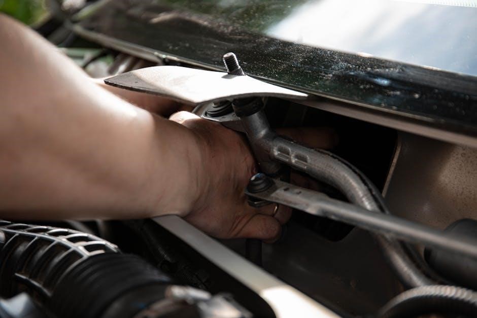
How to Check Transmission Oil Level
Locate the transmission oil plug, typically at the bottom. Use a 3/8 square drive to remove it. Check the oil level and condition using the dipstick or by draining and refilling if necessary.
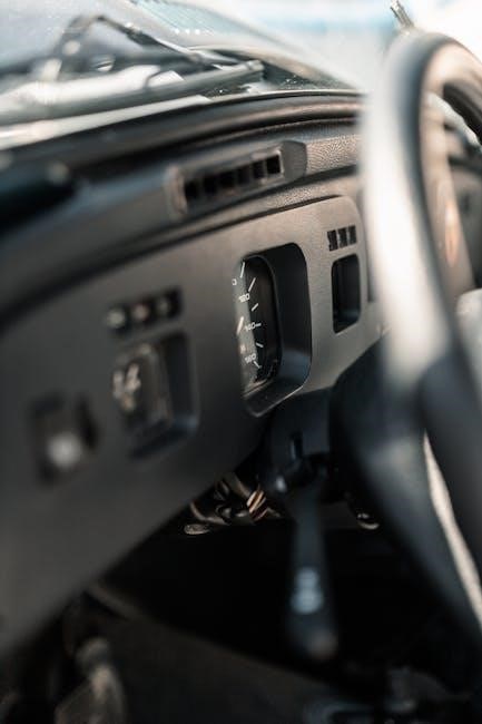
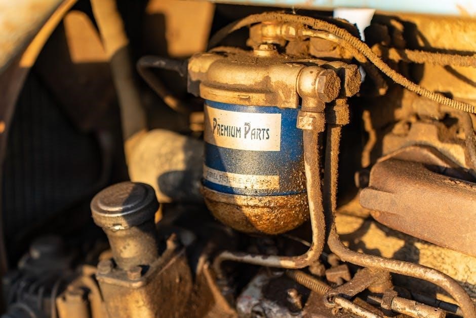
Location of the Transmission Oil Plug
The transmission oil plug is typically located at the bottom of the transmission housing, near the front of the car. It may require a 1/4 ratchet for removal. Additionally, some models feature a fill plug on top, accessible using a 3/8 square drive. Ensure proper tools are used to avoid stripping the plug. Always consult your Honda manual for exact location, as it may vary by model year and transmission type. Proper access ensures safe and effective oil level checks and changes, maintaining your manual transmission’s health and performance over time.
Steps to Check Oil Level and Condition
Start by warming up the engine with a short drive to circulate the oil. Locate the transmission oil plug, typically at the bottom or side, depending on the model. Remove the plug using an appropriate wrench or ratchet. Allow the oil to drain into a pan. Inspect the color and consistency—it should be light amber and smooth, not dark or gritty. Check the level by letting the oil drip freely; it should be just below the plug’s opening. If low, top up with the recommended fluid. Replace the plug securely and dispose of used oil responsibly. Regular checks ensure optimal transmission health and performance.

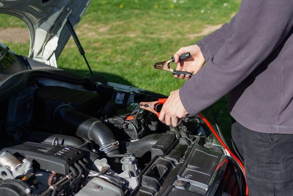
Changing Honda Manual Transmission Oil
Drain the old oil by removing the transmission drain plug, then refill with the recommended fluid. Replace the plug securely to ensure proper sealing and performance.
Tools and Materials Needed
- Drain Pan: A 4-quart capacity pan to catch the old oil.
- Socket Wrench: 3/8-inch drive with the appropriate socket size for the drain plug.
- Breaker Bar: Useful for loosening a tight drain plug.
- Fluid Transfer Pump: For refilling the transmission with new oil efficiently.
- Transmission Fluid: Honda Genuine Manual Transmission Fluid (MTF) or 10W-30/10W-40 engine oil as a temporary alternative.
- New Washers: For the drain plug to ensure a leak-free seal.
- Gloves and Safety Glasses: Essential for protecting yourself during the process.
- Jack and Jack Stands: To safely lift and support the vehicle.
- Ramps: Optional, but helpful for better access to the transmission.
- Torque Wrench: To tighten the drain plug correctly without over-tightening.
- Rags and Funnel: For cleaning up spills and pouring in the new oil neatly.
Having all these tools and materials ready ensures a smooth and efficient oil change process, helping to maintain the health and performance of your Honda’s manual transmission.
Step-by-Step Guide to Oil Replacement
- Warm Up the Transmission: Drive the car for a few minutes to warm the oil for easier draining.
- Locate the Drain Plug: Position the car on level ground, then find the drain plug at the bottom of the transmission.
- Drain the Old Oil: Use a socket wrench to remove the drain plug, allowing the oil to flow into a drain pan.
- Replace the Drain Plug: Once drained, tighten the plug securely with a torque wrench.
- Refill with New Oil: Use a fluid transfer pump to pour in the recommended Honda Genuine Manual Transmission Fluid or 10W-30/10W-40 engine oil.
- Check for Leaks: Start the engine and shift through gears to circulate the new oil, ensuring no leaks from the drain plug.
- Dispose of Used Oil: Responsibly recycle the old oil and clean up any spills with rags.
This process ensures the manual transmission operates smoothly, extending its lifespan and maintaining optimal performance.
Aftermarket vs. Genuine Honda Fluid
Aftermarket oils can be cost-effective and high-performance alternatives to genuine Honda fluid, but may not meet manufacturer specifications. Genuine Honda MTF ensures compatibility and warranty compliance.
Pros and Cons of Using Aftermarket Oils
Aftermarket oils offer cost savings and sometimes enhanced performance features. Brands like Amsoil and Redline provide high-quality alternatives, often exceeding OEM standards. However, they may void warranties and lack Honda-specific formulations. Some users report excellent results, while others prefer the reliability of genuine products. Ensure compatibility and research before switching to avoid potential issues. Always check reviews and manufacturer recommendations to make an informed decision. Balancing cost, performance, and warranty considerations is key when choosing between aftermarket and genuine Honda transmission fluid.

Benefits of Genuine Honda Transmission Fluid
Genuine Honda transmission fluid is specifically formulated to meet the precise needs of Honda manual transmissions, ensuring optimal performance and longevity. It provides superior friction control, wear protection, and thermal stability compared to aftermarket alternatives. Designed to maintain the factory-designed performance, genuine fluid reduces the risk of gear damage and maintains smooth shifting. Additionally, it is warranted by Honda, ensuring reliability and peace of mind. While aftermarket oils may offer cost savings, genuine Honda fluid is engineered for compatibility and durability, making it the recommended choice for maintaining your vehicle’s transmission system in peak condition throughout its lifespan.

Maintenance Tips for Manual Transmission
- Regular oil changes are vital for extending transmission lifespan and ensuring smooth operation.
- Check oil levels periodically to prevent low fluid conditions that can cause damage.
- Avoid extreme temperatures and driving conditions that may degrade the fluid prematurely.
- Always use the recommended fluid type to maintain optimal performance and prevent wear.
Best Practices for Oil Change Intervals
Regular oil changes are crucial for maintaining the health of your Honda manual transmission. Honda recommends changing the manual transmission fluid every 30,000 to 60,000 miles, depending on driving conditions. For vehicles driven under normal conditions, the higher end of this range is suitable. However, if you frequently drive in extreme temperatures, tow trailers, or engage in spirited driving, consider changing the fluid more frequently, around 30,000 miles. Always use genuine Honda manual transmission fluid or equivalent to ensure compatibility and performance. Regular checks of the oil level and condition can also help prevent premature wear and ensure smooth gear operation. Adhering to these intervals will extend the lifespan of your transmission and maintain optimal performance.
Signs of Low or Degraded Transmission Oil
Identifying signs of low or degraded transmission oil is crucial for preventing damage. Common indicators include difficulty shifting gears, grinding or clunking noises, and a noticeable delay in acceleration. If the fluid is low, you may experience slipping or hesitation between gears. Over time, degraded oil loses its lubricating properties, leading to increased friction and wear on internal components. A burning smell or dark, murky fluid during inspections also signals degradation. Regular checks and timely replacements are essential to maintain smooth operation and prevent costly repairs. Always use the correct fluid type to ensure optimal performance and longevity of your Honda manual transmission.

Common Mistakes to Avoid
Using incorrect oil weights or types and neglecting regular oil changes are common mistakes. Always use Honda-recommended fluids to ensure proper transmission function and longevity.
Using Incorrect Oil Weights or Types
Using incorrect oil weights or types can lead to poor transmission performance, gear grinding, or slippage. Honda manual transmissions require specific fluids to maintain viscosity and lubrication properties. Using engine oil like 10W-30 or 10W-40, while sometimes recommended as temporary substitutes, is not ideal for long-term use. These oils may not provide the same level of friction control or wear protection as genuine Honda MTF. Always consult the owner’s manual or manufacturer guidelines to ensure the correct fluid is used. Mixing incompatible oils can compromise transmission health, leading to costly repairs. Proper oil selection is critical for smooth shifting and prolonged transmission life.
Neglecting Regular Oil Changes
Neglecting regular oil changes can lead to severe damage to the manual transmission. Over time, dirt and contaminants accumulate in the fluid, reducing its ability to lubricate gears effectively. This can result in increased wear, grinding noises, or slipping gears. Consistently skipping oil changes accelerates the degradation of transmission components, potentially leading to costly repairs. Honda recommends following the maintenance schedule to ensure the transmission operates smoothly. Regular fluid replacement helps maintain optimal performance, prevents premature wear, and extends the lifespan of the transmission. Ignoring this crucial step can compromise the overall reliability and efficiency of the vehicle’s manual gearbox.

Troubleshooting Transmission Oil Issues
Common issues include leaks, low fluid levels, or degraded oil. Symptoms may involve inconsistent gear shifts or noise. Always use the correct fluid type to avoid damage.
Diagnosing Leaks and Damage
Inspect the transmission oil plug, seals, and gaskets for leaks. Check for oil droplets or stains near these areas; Low fluid levels or discolored oil may indicate internal damage. Regular maintenance helps identify issues early, preventing costly repairs.
Addressing Slipping or Grinding Gears
Slipping or grinding gears in a Honda manual transmission often indicate low or degraded transmission fluid. Check the fluid level and condition, ensuring it meets Honda’s specifications. If the fluid is dirty or insufficient, replace it with genuine Honda MTF or equivalent. Incorrect oil weight, such as using engine oil instead of transmission fluid, can also cause these issues. Grinding gears may signal worn synchronizers or clutch packs, requiring professional inspection. Regular oil changes and using the correct fluid type are essential to prevent these problems. Addressing them early avoids costly repairs and ensures smooth gear operation.
Proper Honda manual transmission oil is crucial for smooth operation and longevity. Regular maintenance ensures optimal performance. Prioritize the right fluid for a durable and reliable drivetrain.
Final Thoughts on Transmission Oil Maintenance
Regular checks and timely fluid changes are vital for maintaining your Honda’s manual transmission. Use only recommended oils to ensure smooth gear shifts and prevent damage. Consistent care extends the life of your vehicle’s transmission, reducing the risk of costly repairs. Always refer to your owner’s manual for specifications and guidelines. By staying proactive, you can enjoy a seamless driving experience and maintain your car’s performance over the years.
FAQs About Honda Manual Transmission Oil
Q: What type of oil is recommended for Honda manual transmissions?
A: Honda Genuine Manual Transmission Fluid (MTF) is highly recommended. However, 10W-30 or 10W-40 engine oil can be used as a temporary alternative if MTF is unavailable.
Q: Can I use engine oil in my manual transmission?
A: Yes, but only as a temporary solution. Engine oil like 10W-30 or 10W-40 is acceptable, but for optimal performance, switch to Honda MTF as soon as possible.
Q: How often should I change the transmission oil?
A: Regular oil changes depend on your driving conditions. Typically, every 30,000 to 60,000 miles is recommended to maintain transmission health and performance.